
Aluminum Die Casting Display Frame Housing for Medical and Electronic Equipment forms the visible and dimensional interface between a display module, protective window and equipment enclosure. Buyers must control more than the outside shape: the screen opening, mounting points, bezel flatness, cosmetic face and coating thickness all influence whether the display sits evenly and looks consistent after assembly.
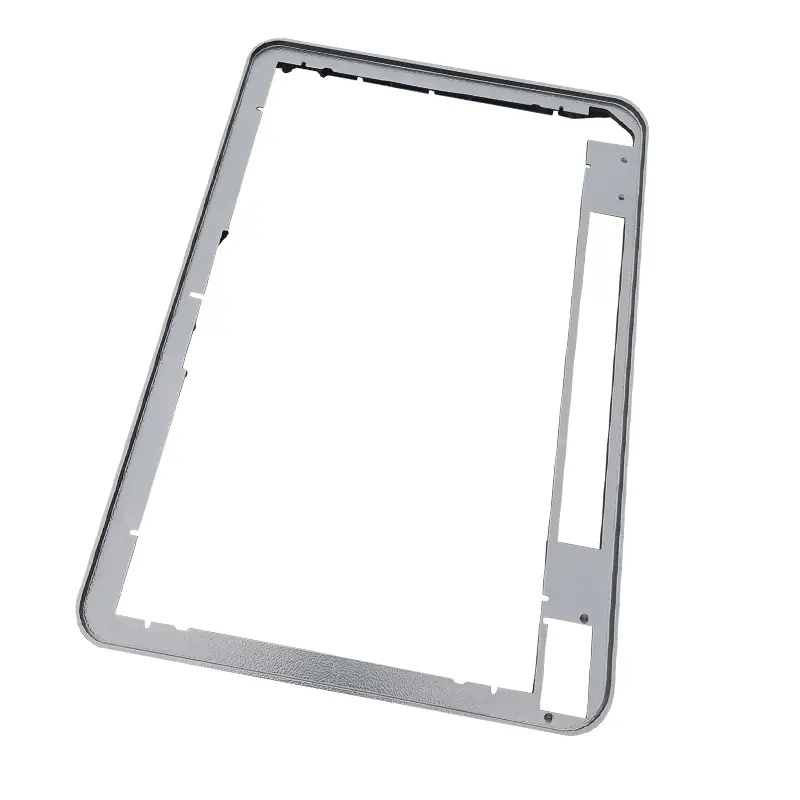
Huabo reviews the frame together with the display, glass or touch panel whenever mating information is available. The DFM discussion identifies the primary locating face, screen-opening tolerance, adhesive or gasket land, screw locations and areas that require electrical continuity. This prevents the casting drawing from controlling dimensions that do not affect fit while leaving a critical aperture or bond line undefined.
| Feature | Why it matters | Manufacturing control | Inspection |
|---|---|---|---|
| Screen aperture | Misalignment remains visible after final assembly | Stable tool insert and machining only where the drawing requires it | Optical or dimensional fixture referenced to mounting datums |
| Front bezel | Broad thin faces can distort or show flow-related marks | Balanced wall thickness, gate review and supported ejection | Flatness check plus agreed visual standard |
| Glass or gasket land | Uneven contact can create gaps or adhesive variation | Define cast or machined surface and protect it during handling | Profile, flatness or contact check according to drawing |
| Rear bosses | Weak bosses can crack during screw installation | Rib support, suitable boss proportions and controlled tapping | Thread gauge and assembly torque validation when specified |
| Coating edge | Buildup can reduce aperture or interfere with the display | Masking and coating-thickness allowance | Post-finish dimensional and appearance check |
“No defects” is not a measurable appearance requirement. A useful specification marks the front visible zone, secondary side surfaces and concealed rear area, then defines acceptable limits for flow marks, parting lines, ejector traces, scratches and color variation. Gate and overflow positions can be moved away from the most visible areas where tooling and filling conditions permit. A signed finish sample is valuable for repeat orders because it gives purchasing, production and inspection teams the same reference.
The complete outside frame does not always require one tight flatness value. The critical condition may be the smaller display-contact land or a set of mounting pads. Huabo recommends tying these functional zones to a clear datum system. Rib layout, wall transitions and ejection support are then reviewed around that requirement. If CNC machining is necessary, the fixture supports the frame at defined points so clamping does not temporarily straighten a distorted part.
Die cast and trim the frame while protecting the front bezel from handling damage.
Remove flash from the aperture, boss and parting-line areas.
Machine critical mounting pads, locating holes, threads or display-contact surfaces from the approved datums.
Clean the part using a process compatible with the selected coating.
Mask threaded holes, grounding areas, adhesive lands or precision fits identified on the finish drawing.
Apply paint, powder coat or another specified finish and inspect appearance under agreed conditions.
Pack frames with separators so front faces cannot rub during transport.
For medical or laboratory equipment, the customer may require cleanable surfaces, controlled gaps and documented material or finish information. For electronic equipment, grounding points, cable clearance and electromagnetic shielding interfaces can be important. Huabo manufactures to the customer-approved drawing and quality plan; regulatory or product-level certification requirements should be supplied with the RFQ so they can be included in the review.
First-article reporting should connect the screen aperture, mounting holes and display-contact surface to the same datum structure used by the customer. Cosmetic inspection is recorded separately from dimensional results. During production, a dedicated fixture may be appropriate for rapid aperture and mounting checks, while a CMM supports periodic validation or engineering changes. Coated parts are checked again where coating thickness can affect fit.
Please send 3D and 2D files, the display or glass interface drawing, required alloy, finish specification, cosmetic zoning, annual volume and packaging expectations. Identify any adhesive, gasket, grounding or cleanability requirement. Related support includes aluminum die casting, precision machining, painting and surface finishing and dimensional inspection.
Can the front bezel be supplied ready for final assembly?
Yes. The scope can include casting, deburring, CNC machining, cleaning, masking, coating, inspection and protective packing.
Should the screen opening be cast or machined?
The choice depends on tolerance, appearance, volume and geometry. DFM compares a stable tool insert with post-machining before the process is fixed.
How is coating buildup around the display controlled?
The finish drawing defines masking and the dimensions that apply after coating. Critical apertures and contact lands can then be verified on the finished part.
 RELATED
RELATED
RELATED
 RELATED
 RELATED
Tel: +86 18868921505
Email: lijianguo@cxhuabo.com
Address: Yiheng Road, Changhe Town, Cixi City, Ningbo, Zhejiang Province, China

Scan wechat
Copyright © 2022 Cixi Huabo Machinery Co., Ltd
SitemapThis website uses cookies to ensure you get the best experience on our website.

 Español
 Pусский
 Français
 日本語
日本語


 WhatsApp
 Phone
Phone