
Improving aluminum die casting quality is not a final-inspection exercise. By the time a leak appears on a machined sealing face, a threaded boss exposes porosity, or a housing becomes unstable after coating, the real cause may already be locked into the part geometry, die layout, filling pattern, cooling balance or machining datum strategy. Sorting finished castings can contain a shipment, but it cannot make an unstable process capable.
This guide is written for sourcing teams, design engineers and quality engineers who need to move a custom aluminum die casting from RFQ to repeatable production. It explains which decisions must be made before tooling, how to distinguish common defect families, which inspection method answers which risk, and what evidence should be reviewed before mass-production approval.
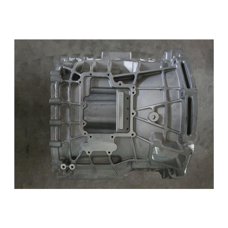
There is no useful universal definition of a “good casting.” A cosmetic electronics cover, a gearbox housing, a load-carrying bracket and a valve body do not fail in the same way. The drawing may show the same general material, yet the critical zones and acceptance evidence can be completely different.
Before discussing gate position or inspection frequency, divide the part into functional zones:
This zoning step changes the entire quality plan. A small pore outside a functional area may have no effect, while a much smaller connected pore across a sealing wall can make the part unusable. Likewise, a general profile tolerance does not replace a specific flatness or position requirement on an assembly datum.
Published die casting design ranges are useful during early concept review, but they are not automatic capability guarantees. Part size, flow length, alloy, die construction, thermal balance, machine selection, surface texture and tool life all affect what is practical. The following values are common engineering starting points for discussion and must be confirmed through project-specific DFM and die trials.
| Design item | Typical starting direction | Why it matters | What the buyer should confirm |
|---|---|---|---|
| Nominal wall thickness | About 2.0-4.5 mm for many structural housings; thinner local walls may be feasible on small, favorable geometries | Long thin flow paths risk incomplete fill; isolated thick sections cool slowly and can promote shrinkage | Flow length, transition geometry, local load and whether a thick boss can be cored or ribbed |
| External draft | Often around 1-2 degrees as an early reference | Insufficient release angle can cause drag marks, distortion and die wear | Draw depth, surface texture, cosmetic limits and which side retains the casting |
| Internal draft | Often around 1.5-3 degrees; deep or textured features may need more | Internal surfaces generally grip the core more strongly during ejection | Core depth, polishing direction, ejector arrangement and permitted witness marks |
| Internal fillet radius | Roughly 0.4-1.5 mm is a common early range, then adjusted to wall and tool geometry | Sharp corners concentrate stress, restrict flow and reduce die durability | Load path, adjacent wall thickness and cutter or insert access |
| Machining allowance | Frequently about 0.5-1.5 mm where machining is genuinely required | Too little stock risks unclean surfaces; too much stock increases cycle time and can open deeper porosity | Casting variation, datum strategy, sealing requirement and allowable cut depth |
| As-cast tolerance | Set by feature size and process capability, not a single blanket value | Over-tight general tolerances increase tool complexity, inspection cost and false rejection | Critical-to-function dimensions, measurement method, datum system and machining alternative |
The main objective is not to force every section to the same thickness. It is to avoid sudden thermal masses and unpredictable flow. A heavy boss attached directly to a thin panel can remain hot after the panel has solidified. That combination can produce shrinkage around the boss, distort the panel and create variation at a threaded feature. A cored boss supported by proportionate ribs often provides a better load path with less local metal mass.
Ribs should strengthen a surface without becoming a second thick wall. Their junctions, ends and intersections deserve special review because multiple sections meeting at one point can become a hot spot. The design team should also consider where ejector pins can act without bending the casting or marking a cosmetic surface.
The parting line determines where flash is formed, how the casting is trimmed, which features can be produced with straight-pull die steel and where slides may be required. It can also influence dimensional relationships across the two die halves. Moving the parting line after tool design has started is rarely a small change, so its effect on sealing faces, cosmetic areas and machining datums should be agreed during DFM.
Huabo's die casting and manufacturing capabilities page gives buyers a starting view of the processes that can be coordinated around a custom part. The drawing review still needs to identify the requirements that are unique to the project.
Alloy choice affects filling behavior, mechanical performance, corrosion behavior, machinability, surface finishing and the way the casting responds to thermal cycles. It should not be selected only because a previous part used the same grade.
| Alloy direction | Common reason for consideration | Questions before approval |
|---|---|---|
| ADC12 | Widely used in Asia for general high-pressure die cast housings and components because it offers a practical balance of castability and machinability | Is the customer specification based on JIS chemistry? Are coating, corrosion and mechanical requirements compatible with the selected temper and process route? |
| A380 | Common North American general-purpose die casting alloy for housings, brackets and industrial components | Does the drawing call out an ASTM or customer-specific chemistry? Are the material certificate and conversion requirements clear? |
| A413 | Often considered when fluidity and pressure-tight casting behavior are important | Will the part be machined, coated or exposed to a specific fluid? What leak-test method and acceptance limit apply? |
These descriptions are selection directions, not substitutes for the customer's material standard. The RFQ should state the required grade, governing specification, restricted substances and any mechanical or corrosion tests. If the design team is still choosing a material, the supplier needs the service temperature, load, environment, finishing route and pressure-tightness requirement before recommending an alternative.
A visually smooth surface does not prove that the interior is suitable for machining or sealing. Internal quality is shaped by how air leaves the cavity, how the metal front joins, where pressure can still be transmitted during solidification and how heat is removed from heavy sections.
The ingate should direct metal through the cavity without creating avoidable turbulence or forcing the final metal front to close at a critical sealing or load zone. Runner balance matters in multi-cavity tools because unequal filling can create different defect patterns in nominally identical parts. Overflows are not scrap pockets added at random; their location should help collect cold or contaminated metal and support cavity venting.
Air must have a controlled exit path. Blocked vents, poorly located vents or lubricant vapor can leave gas trapped inside the casting. Vacuum assistance may reduce gas entrapment on suitable parts, but it cannot correct a fundamentally poor flow path, excessive spray, a leaking vacuum circuit or an unstable shot profile. The project team should define whether internal integrity will be checked by sectioning, radiography, leak testing or another method rather than assuming that the presence of vacuum guarantees acceptance.
Alloy identification, charge control, melt handling and dross management influence inclusions and consistency. At the die, local temperature matters as much as a single displayed average. A cold area can cause premature freezing and cold shuts; an overheated insert can encourage soldering, sticking or local shrinkage. Cooling circuits, spray pattern, cycle time and insert condition therefore need to be treated as connected controls.
Several defects can look similar after blasting, machining or coating. The location, shape, depth and process timing are often more useful than the defect name written on a rejection tag. The matrix below shows a practical first review. It does not replace a controlled root-cause investigation.
| Observed symptom | Likely defect family | Evidence to collect | First review direction |
|---|---|---|---|
| Rounded cavities exposed after machining; sometimes smooth inside | Entrapped gas or vapor | Defect location by cavity and shot, vent condition, spray record, fracture or section image, leak result | Review metal-front closure, vent/vacuum performance, lubricant amount and shot transition |
| Irregular or dendritic void in a heavy section | Shrinkage porosity | Section thickness map, thermal pattern, gate freeze behavior, local cooling and sectioned sample | Reduce isolated thermal mass, improve feed/pressure transfer and rebalance local cooling |
| Visible seam where two metal fronts meet | Cold shut | Seam position, fill simulation if available, die temperature, cycle interruption and alloy condition | Review flow path, venting, local die temperature and whether the fronts meet in a critical zone |
| Thin metal at the parting line or around a slide | Flash | Flash thickness and location, clamp record, die fit, insert wear and shot consistency | Check die closure and wear before increasing clamp or changing process settings |
| Metal adheres to die steel; dragged or torn surface after ejection | Soldering or sticking | Insert temperature, alloy chemistry, release pattern, draft, surface condition and cycle trend | Review hot spots, draft, die surface treatment, lubrication and local metal velocity |
| Raised bubbles after baking or powder coating | Blistering from subsurface gas expansion | Pre-coating surface condition, bake temperature and time, porosity section, coating preparation | Trace the gas source and review whether the casting and coating thermal cycle are compatible |
| Unfilled edge, incomplete rib or rounded corner | Misrun or premature freeze | Defect frequency by cavity, local die temperature, fill path and cycle time | Review section thickness, flow length, gate delivery and thermal stability |
| Part meets size after casting but moves after machining or coating | Residual stress or unbalanced geometry | Measurement at each process stage, fixture clamping, stock removal pattern and thermal exposure | Review cooling balance, ejection, datum choice and symmetric machining sequence |
The important discipline is traceability. Record the cavity, machine, die, shift, alloy lot and process stage connected to the defect. Without this information, a team may change several variables at once, obtain a temporary improvement and still fail to establish the real cause.
Machining does more than create accurate dimensions. It changes the stress balance of the casting and removes the surface layer that may be denser than the interior. A deep cut through a heavy section can reveal porosity that was invisible on the as-cast part. A fixture that clamps an unstable wall can produce dimensions that look acceptable in the fixture and move after release.
The casting drawing and machining drawing should therefore be reviewed together. Identify the first locating surfaces, the sequence in which material will be removed, the stock required to clean up each surface and the features that must remain related to a common datum. Around sealing faces and threaded ports, mark the maximum permitted machining depth and the internal-defect acceptance zone.
For projects that require secondary operations, review the available tooling, CNC machining and finishing services as one production route. Huabo's custom aluminum die casting processing page also shows how casting and downstream operations can be considered together at the RFQ stage.

Inspection adds value only when it answers a defined question. A CMM can confirm geometry, but it cannot prove pressure tightness. A leak test can detect a connected leakage path, but it does not provide a complete map of every internal pore. The control plan should connect the defect risk, critical zone, method, sample frequency and acceptance limit.
| Method | What it can verify | Important limitation or planning point |
|---|---|---|
| Visual inspection with reference samples | Flash, cold shuts open to the surface, drag marks, coating defects and cosmetic limits | Lighting, viewing distance and acceptance examples must be defined to reduce subjective decisions |
| CMM, height gauge or dedicated gauge | Critical dimensions, position, profile, flatness and functional relationships | Results depend on datum alignment, fixturing, temperature and measurement strategy |
| Spectrometer | Alloy chemistry verification | The material standard, sampling point and lot traceability must be specified |
| Sectioning and metallographic review | Local porosity shape, distribution and microstructural evidence | Destructive and local; the section must pass through the risk zone to be meaningful |
| X-ray or CT when project-specified | Internal discontinuities and their location within the inspected resolution | Acceptance zones, image quality, orientation and qualified service route must be agreed; not every pore is functionally relevant |
| Air or liquid leak test | Whether a connected path exceeds the specified leak limit under test conditions | Pressure, medium, stabilization time, test time, temperature and limit must be recorded |
| Coating thickness and adhesion checks | Finish consistency and bond performance against the coating specification | Substrate preparation, cure cycle and measurement location influence the result |
Huabo's machining and inspection equipment overview includes dimensional and material-verification resources such as CMM, projector and spectrometer equipment. Project-specific methods such as radiography, CT or leak testing should be confirmed during quotation rather than assumed.

A sample is useful only when it represents the intended production route. A hand-polished casting made with temporary settings and measured without the planned machining fixture may look impressive but provide weak evidence for repeatability. A stronger approval route has clear gates:
Consider a hypothetical aluminum gearbox housing with a gasket face, two bearing bores, several threaded holes and an external powder-coated surface. The wrong approach is to apply “no porosity” to the entire casting and place a tight general tolerance on every dimension. That creates an expensive specification without showing how the housing will actually fail.
A better plan first identifies the gasket face and walls around the oil cavity as pressure-sensitive zones. The two bearing bores and their relationship to the mounting datum become critical geometry. The threaded bosses are reviewed for local wall mass and machining depth. The visible exterior receives a separate cosmetic standard for flow marks, ejector witnesses and coating.
The inspection plan can then use CMM measurement for the bearing and datum relationship, a recorded leak test for the oil cavity, controlled machining stock around the gasket face, visual reference samples for the coated exterior and periodic destructive or radiographic checks only where internal evidence is needed. Each method answers a different risk. This is more actionable than demanding every inspection on every part.
A detailed RFQ allows suppliers to quote the same scope and expose manufacturing risks before tooling. Include:
For an application-specific review, compare these inputs with Huabo's quality control workflow and relevant ADC12 aluminum die casting components. A drawing review is more useful than selecting a process from a product photo alone.
Porosity is not one defect. Rounded, smooth cavities often indicate trapped gas or vapor, while irregular cavities in heavy sections may indicate solidification shrinkage. The correct response depends on defect shape, location and process history. Venting, spray, flow pattern and vacuum performance are reviewed for gas-related defects; thermal mass, pressure transfer and cooling balance are central to shrinkage review.
Machining may remove a shallow surface imperfection, but it can also open subsurface cavities and create a leakage path. It is not a reliable correction for internal porosity. Pressure-sensitive and cosmetic machining zones should be identified before tool design so flow, stock and inspection can be planned around them.
No. ADC12 is a common general-purpose choice, but the service environment, strength, corrosion, thermal performance, pressure tightness, machining and finishing requirements may point to another grade. The final selection must follow the customer's specification and project risks.
No. Vacuum can reduce trapped gas when the die is sealed and the filling system is designed correctly, but it does not eliminate shrinkage, inclusions or every gas source. Acceptance still requires a defined method such as leak testing, sectioning or radiographic inspection in the relevant zone.
Specify the function, critical zone, defect type, inspection method and acceptance limit. “Good surface” and “no porosity” are not repeatable requirements. A useful specification might define a gasket zone, leak-test pressure, stabilization time, test duration and allowable leak rate, along with the drawing revision and sampling plan.
Approve the drawing revision, alloy, representative samples, dimensional report, full secondary-operation route, critical inspection results, cosmetic standard, packaging and process-change rules. The approved sample should be traceable to the die cavity and trial condition.
Consistent aluminum die casting quality comes from connected decisions: geometry that can fill and release, a die that controls flow and heat, machining datums that do not distort the part, and inspection methods linked to actual function. The earlier these decisions are made, the less the project depends on sorting and repair after production.
Send Huabo your 3D model, 2D drawing, alloy requirement, annual quantity and critical quality zones for a project-specific DFM and quotation. Use the contact page to request a manufacturing review.
Engineering note: the dimensional ranges in this article are common early design references, not guaranteed production limits. Final values and inspection capability must be confirmed against the specific part, tooling concept, material standard and approved control plan.
Tel: +86 18868921505
Email: lijianguo@cxhuabo.com
Address: Yiheng Road, Changhe Town, Cixi City, Ningbo, Zhejiang Province, China

Scan wechat
Copyright © 2022 Cixi Huabo Machinery Co., Ltd
SitemapThis website uses cookies to ensure you get the best experience on our website.

 Español
 Pусский
 Français
 日本語
日本語


 WhatsApp
 Phone
Phone
Comment
(0)